

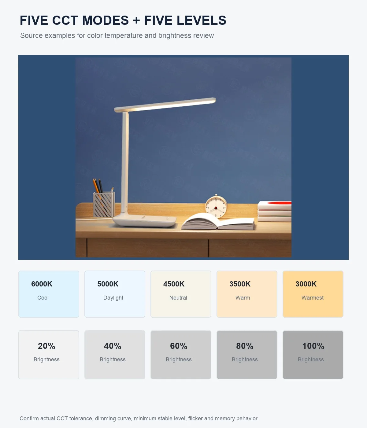
A desk lamp specification says “five brightness levels: 20%, 40%, 60%, 80%, 100%.” Does that mean the work surface receives exactly those percentages of the maximum illuminance? It might—but the labels alone do not prove it.
For a bulk buyer, the useful question is whether the dimming system behaves predictably in the configuration customers will receive. That includes the output at each setting, the lowest stable level, the transition between settings, temporal light modulation, startup state, memory, and interaction with the supplied power system.
All numerical results in this guide are fictional. They illustrate a review method and are not RoyeLamp test data, universal tolerances, or claims about a particular production model.
1. A control percentage is not automatically an output percentage
A brightness label may describe a user-interface step, a driver command, a duty-cycle setting, or a marketing convention. None of those definitions automatically establishes illuminance on the desk. Ask the supplier what the percentage refers to and verify the delivered result on the approved sample.
For a stepped lamp, record every level. For a slider or long-press control, choose repeatable checkpoints such as minimum, 25%, 50%, 75%, and maximum, plus any point where the transition looks uneven. Mark how the position is set; a finger location on an unmarked slider is not a reproducible test coordinate.
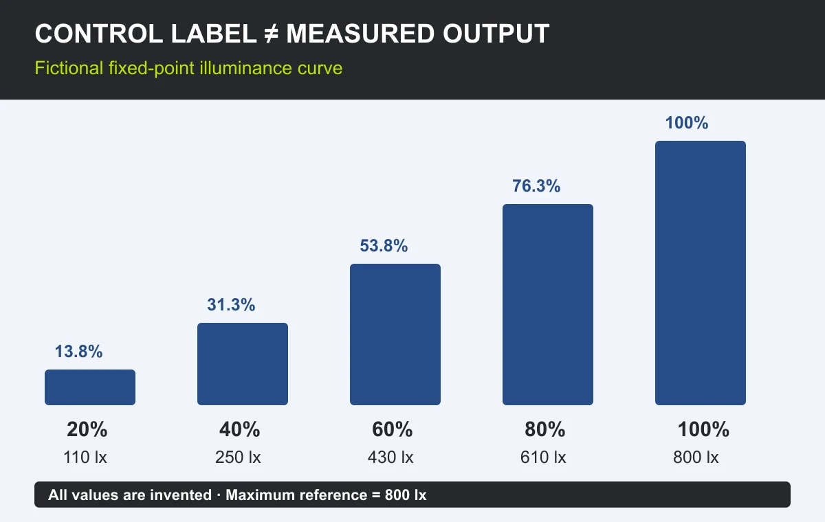
The table below shows a fictional five-level sample measured at one fixed point. The maximum reading is 800 lx, so the relative reading for each level is calculated as measured illuminance ÷ 800 × 100%.
| Control label | Fictional reading at the fixed point | Relative to measured maximum | What the buyer learns |
|---|---|---|---|
| 100% | 800 lx | 100% | Reference maximum for this setup |
| 80% | 610 lx | 76.3% | Below the label, but still a clear step |
| 60% | 430 lx | 53.8% | Output continues to increase monotonically |
| 40% | 250 lx | 31.3% | Label and measured ratio are not identical |
| 20% | 110 lx | 13.8% | Lowest step in this fictional sequence |
The curve is monotonic: every higher setting produces more light than the one below it. It is not linear with the printed labels. That may be acceptable if the user experience and agreed limits are met. Do not reject or approve the sample merely because the numbers are nonlinear; decide what the range and spacing need to accomplish.

Illuminance at one point is useful for comparing settings when geometry is fixed. It is not the same as total luminous flux, and it does not describe the whole work surface. If coverage matters, keep a separate grid check using the method in the desk lamp illuminance guide.
2. Define “minimum” as a stable operating condition
A lamp that briefly reaches a very low output but pulses, drops out, changes colour, or cannot return to the same point does not have a useful minimum there. After warm-up, hold the sample at its lowest setting for an agreed observation period. Repeat the move from maximum to minimum and from off to minimum if the control permits it.
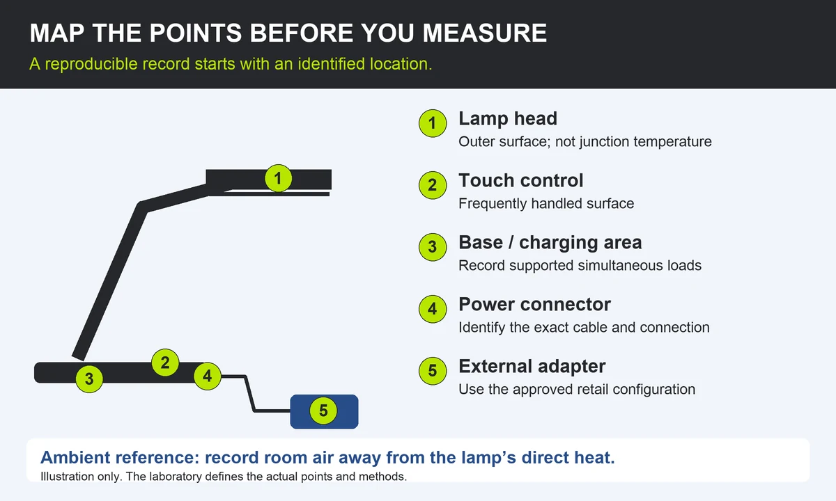
Record the actual input adapter and cable. A sample powered from a laboratory supply or a convenient charger has not established behaviour with the retail configuration. If the lamp also powers USB or wireless-charging functions, repeat the agreed dimming checks under the simultaneous-use conditions claimed for the product.
State the lamp geometry, colour mode, input source, warm-up time, ambient condition, measurement point, minimum illuminance, percentage of measured maximum, observation duration, and any visible instability, noise, reset, or shutdown. “Dims very low” is not an inspection record.
Check several samples, not only the development unit. Component tolerances can affect the bottom end of a dimming range. The buyer and supplier should agree how many samples are checked, how variation is handled, and whether a borderline result triggers adjustment, sorting, or rejection.
3. Check temporal light modulation at maximum and dimmed levels
Light output can vary rapidly over time even when the average lux reading appears stable. The U.S. Department of Energy uses the term temporal light modulation (TLM) and explains that the driver, loading, dimming level, waveform, modulation depth, and frequency can all matter. A result at full output cannot automatically represent the lowest setting.
Do not rely on one slow-motion phone video as the acceptance method. Camera exposure and frame rate can reveal banding in some conditions, miss it in others, or create patterns that do not describe human perception. A phone recording can be a screening clue; it is not a substitute for an agreed measurement and metric.
CIE TN 012:2021 gives recommendations for measuring periodic waveforms and reporting TLM consistently. The CIE page also cautions that the Technical Note provides recommendations rather than standardization. Specify the applicable market requirement, measurement method, instrument, settings tested, waveform record, metrics reported, and acceptance limits with a competent lighting laboratory.
| Condition | Keep fixed or record | Why it belongs in the report |
|---|---|---|
| Maximum and each stepped level | Same colour mode, input source, geometry, and measurement method | Full-output performance may not represent dimmed operation |
| Stepless control checkpoints | Repeatable positions and direction of approach | “Halfway” needs a reproducible definition |
| Combined-function load | Lighting plus the agreed charging or display functions | Shared power conditions may change behaviour |
| Input variation within rated use | Approved adapter, cable, and agreed supply conditions | The complete retail power system is the product under review |
| After warm-up and repeated operation | Timing, sample count, and repetitions | Separates a one-off demonstration from repeatable evidence |
No single number describes every temporal effect or application. DOE distinguishes direct flicker, the stroboscopic effect, and the phantom-array effect, and notes that one metric cannot predict every observer, camera, or use condition. Avoid turning an unexplained “flicker-free” label into a blanket claim.
4. Approve what the control does after every transition
Dimming is also control logic. Write a short sequence that another inspector can repeat without asking the product manager what was intended.
- Power on: Does the lamp start off, at a fixed level, or at the last used setting?
- Power interruption: Does behaviour change after the touch control is used, the adapter is unplugged, or mains power is switched?
- Colour-mode change: Is brightness retained separately for each colour mode or shared across modes?
- Minimum-to-off boundary: Can the user reach off accidentally while sliding or holding the dimming control?
- Step response: Are there duplicate levels, sudden jumps, overshoot, delayed response, or missed commands?
- Timer or night light: Does the main-light setting remain defined after the secondary function ends?
The touch-control reliability checklist covers active zones, repeated input, contamination, and control response. Use it alongside this optical review rather than merging the two into one vague “function test.”
For a current product example, the RY26-A page lists five source-stated brightness levels—20%, 40%, 60%, 80%, and 100%—and tells buyers to confirm dimming behaviour and minimum stable output on the sample. The fictional curve in this article is not an RY26-A measurement and should not be used as its acceptance record.
5. Convert the approved sample into a production check
Attach the dimming record to the identified sample, firmware or control-board revision, LED board, driver, adapter, cable, diffuser, and colour-mode configuration. A change to any of these may justify targeted rechecking because the visible curve or temporal behaviour can change without altering the housing.
Keep raw readings instead of only “pass.” For stepped lamps, retain the individual output and temporal results at every setting. For stepless lamps, retain the selected checkpoints, the method used to locate them, and observations from a complete sweep. Record the instrument, calibration status, test date, operator, sample IDs, and environmental conditions needed to repeat the comparison.
At pre-shipment inspection, verify the control sequence and selected output points against the latest authorized record. If full laboratory TLM measurement is not part of routine inspection, define which production evidence is reviewed and what change or symptom triggers laboratory retesting. The pre-shipment inspection guide explains how to connect sample identity, sampling, and escalation.
Please confirm the dimming method for our selected lamp configuration. Identify every stepped level or the repeatable checkpoints for a stepless control. Provide output readings using a fixed geometry and state the maximum-reference calculation. Report the lowest stable setting, transition behaviour, startup and memory logic, and TLM test method and results at the agreed levels. Identify the lamp, LED board, driver/control revision, adapter, cable, colour mode, diffuser, sample IDs, and any combined-function loading used. List changes that require reapproval before production.
Questions buyers often ask
Should a “20%” setting measure exactly 20% of maximum lux?
Only if the specification defines the label that way and sets an agreed tolerance. Otherwise, treat it as a control label and review the measured curve, usable range, and step spacing.
Is stepless dimming always better than five levels?
No. Stepless control offers finer adjustment, while defined levels can be easier to reproduce and inspect. The better choice depends on the customer, interface, and acceptance method.
Does a stable lux meter reading prove the lamp is flicker-free?
No. An ordinary average illuminance reading does not characterize rapid light variation. Use an appropriate TLM measurement method and the metrics required for the target market and application.
Send the dimming brief with your sample enquiry
Share the selected model, target market, control style, required brightness range, power configuration, combined functions, and acceptance method. Ask RoyeLamp which dimming options and evidence can be confirmed for that configuration.
By Helen. Sources and product details checked September 14, 2026. This is an editorial buyer guide, not a laboratory report or a statement that every test, dimming range, or control option is available. Requirements and evidence must be confirmed for the selected order.
