

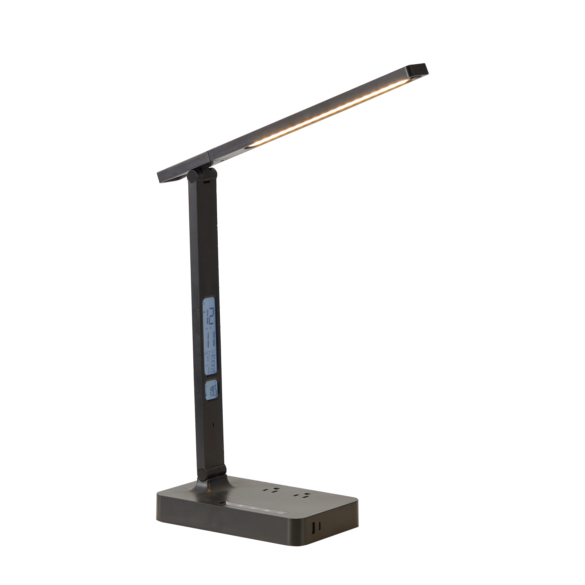
An adjustable LED desk lamp can look solid on a sample-room table and still develop head drop, loose joints, squeaks, cracked housings, or cable damage after repeated use. For a wholesale buyer, the useful question is not whether a supplier says the hinge is “durable.” It is whether the ordered construction can complete a defined movement profile and still meet measurable acceptance limits.
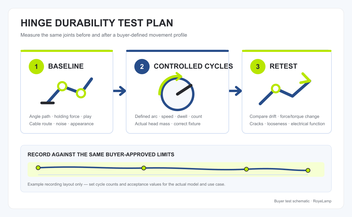
1. Map the movement architecture before writing the test
“The hinge” is often several different mechanisms. A foldable base lamp may have a lower arm pivot, an upper arm pivot, and a rotating head. A clamp lamp may add a removable head connection, several articulated joints, and a clamp that can loosen independently of the arm. Testing the lamp as one unnamed mechanism makes a failure hard to diagnose and a corrective action hard to verify.
Create a joint map and give every moving point a stable ID, such as J1 at the base, J2 at the middle arm, and J3 at the head. For each joint, record its intended axis, usable angle range, normal direction of operation, end-stop behavior, load path, fastener or friction mechanism, and nearby cable route. Photograph the starting position and all end positions. If the instructions prohibit a movement, do not turn that misuse into the normal cycle without defining a separate abuse test.
| Joint-map field | What to define | Why the buyer needs it |
|---|---|---|
| Joint ID and axis | Exact moving point and direction of rotation | Prevents different operators from cycling different parts |
| Start and end positions | Angles or physical reference points, including allowed stops | Makes each cycle repeatable and reveals overtravel |
| Applied load | Production-intent head, arm, cable, accessories, and mounting | Joint demand changes when mass or leverage changes |
| Adjacent risks | Cable bend, connector movement, pinch point, clamp slip, housing stress | A joint can retain position while damaging another component |
2. Build a numerical baseline on untouched samples
A post-cycle statement such as “still works” has little value without a starting measurement. Use production-intent samples that have been conditioned in a defined environment, then record the same attributes that will be checked after cycling. The measurement method matters as much as the number: pulling at a different distance from the pivot changes the measured force, and reading an angle from a different reference surface changes the apparent drift.
| Attribute | Practical method | Record in the report |
|---|---|---|
| Usable movement range | Measure from defined product datums without forcing past the stop | Minimum and maximum angle for each joint |
| Actuation force or torque | Move at a defined speed; measure at a fixed lever arm or use a suitable torque method | Peak and running value, direction, tool, distance, and units |
| Position retention | Set the lamp at a defined worst-case extension and observe under its own specified load | Starting angle and drift after a defined time |
| Free play or backlash | Apply a small defined reversing load without intentionally moving the joint | Linear displacement at a defined point or angular movement |
| Noise and feel | Operate through the normal range in a controlled room | Squeak, clicking, binding, stick-slip, or asymmetric movement |
| Physical condition | Inspect in defined lighting and magnification where needed | Cracks, whitening, rubbing, fastener position, gaps, and finish damage |
| Cable and electrical function | Inspect the moving cable route and run all functions before cycling | Pinch, abrasion, connector strain, intermittency, controls, light, and outputs |
3. Define exactly what one cycle means
Cycle count by itself is not a test specification. A cycle through a small central arc at low speed is easier than a full movement that approaches both stops. Moving one joint at a time may not represent a user who folds several sections together. A high-speed machine can also add heat, impact, and inertia that a person would not create.
Write one cycle as an executable sequence. Include the starting position, joints moved, direction, angle or reference stop, speed, dwell, return path, and any pause between cycles. State whether the light is powered, whether charging or USB functions are loaded, and whether the cable is installed exactly as in production. If the intended product is frequently folded for storage, include that fold-and-open sequence. If it is mainly repositioned during work, build a representative mix of smaller adjustments and occasional full-range movements.
Parameters that must appear in the protocol
- Cycle definition: every movement that counts as one cycle, including return movement.
- Movement profile: joint sequence, angle, speed, dwell, acceleration, and approach to end stops.
- Sample configuration: head, arm, cable, accessories, adapter, base or clamp, and production-intent fasteners.
- Mounting: base support or representative desk edge, clamp tightening method, orientation, and fixture stiffness.
- Environment: conditioning time, temperature, humidity where relevant, and powered or unpowered state.
- Checkpoints: planned inspection intervals and the stop-test rule for unsafe or destructive failures.
- Acceptance limits: allowed change in force or torque, drift, play, noise, appearance, cable condition, and function.
4. Make the fixture reproduce product use
The fixture should hold the lamp as the product is intended to be held while avoiding artificial reinforcement. A foldable base lamp needs its real base and production-intent head mass. A clamp lamp needs a representative edge with specified thickness, surface material, underside clearance, and tightening method. For clamp models, mark the clamp position so the report can separate arm-joint movement from clamp slip.
Connect the actuator at a defined point and align it with the intended movement. Side loading a joint designed for rotation can create a failure that users would not produce. Conversely, supporting the head too generously can hide the bending moment the joint sees in service. Video the fixture at low speed before the endurance run and compare the path with manual operation of the approved sample.
If a machine cycles several joints, verify that one actuator does not push another joint past its normal stop. Recheck fasteners and fixture alignment at planned checkpoints, but do not retighten the product during the run unless the protocol explicitly treats retightening as a failure or maintenance event.
5. Retest the baseline and diagnose the change
At the end of the planned cycling, allow the sample to return to the defined conditioning state. Repeat the baseline with the same tools, datums, lever arm, direction, speed, load, and observation time. Report both the absolute final value and the change from baseline for every sample. Averages alone can hide one severe failure.
| Observed symptom | Areas to investigate | Buyer response before approval |
|---|---|---|
| Head drops or angle drifts | Friction washer wear, fastener migration, spring relaxation, plastic creep, excessive leverage | Identify the affected joint; review material, stack-up, and fastening; repeat the revised test |
| Actuation becomes much lighter or heavier | Wear debris, galling, lubricant migration, deformation, misalignment | Compare each direction and sample; inspect disassembled parts after functional evidence is recorded |
| Increasing play or rattle | Hole wear, pin clearance, insert movement, loose fastener, cracked boss | Set a measurable play limit and confirm the production control method |
| Clicking, squeak, or stick-slip | Surface finish, washer stack, dry contact, cable rubbing, part interference | Locate the source; do not accept noise based only on continued movement |
| Crack, whitening, or gap growth | Stress concentration, overtravel, screw torque, resin choice, molding condition | Stop if safety could be affected; contain related production and validate corrective action |
| Light or output becomes intermittent | Cable bend radius, pinching, conductor fatigue, connector retention, solder strain | Treat electrical interruption as a functional failure even when the hinge still holds |
| Clamp position moves | Pad grip, tightening method, desk surface, load direction, clamp structure | Separate mounting compatibility from joint durability and test both against their own limits |
6. Apply the method to the actual lamp architecture
The same framework leads to different protocols because products move differently. The two examples below show why a model number and a joint map must appear on every test report.
Foldable base lamp: RY26-A
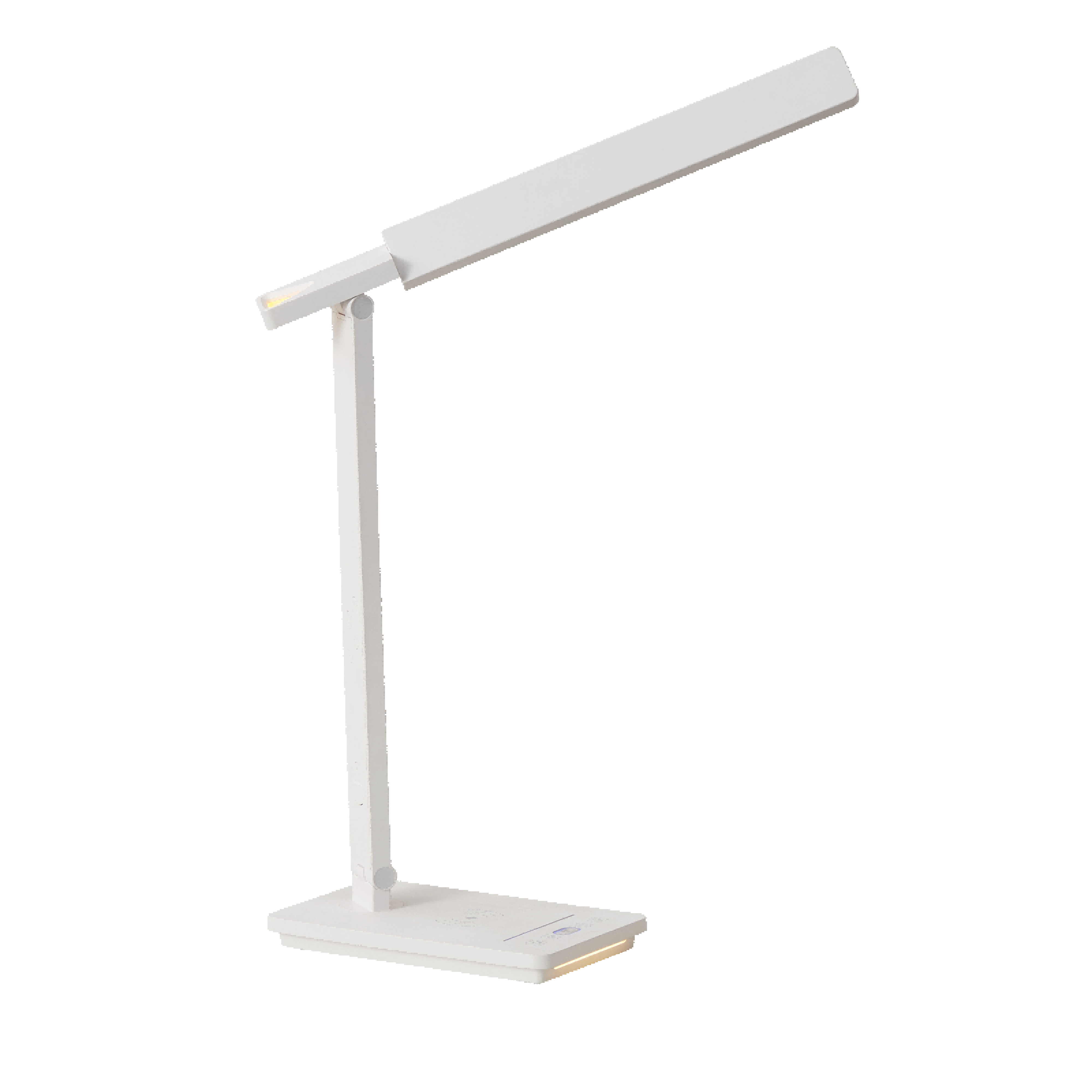
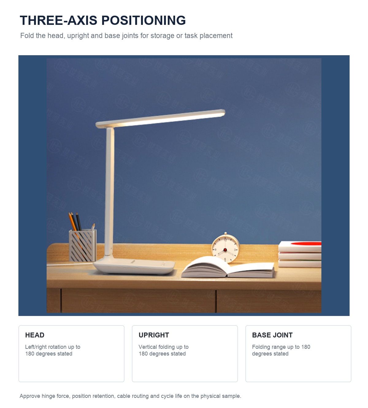
The RY26-A foldable eye-care desk lamp is source-listed with three adjustment axes and up to 180-degree movement at the illustrated joints. Its protocol should identify each axis, reproduce the intended storage fold, check base stability at extended positions, and inspect the internal or routed cable near every moving point. The illustrated angles are product information to verify on the ordered sample; they are not a substitute for approved angle tolerances.
Articulated clamp lamp: RY229-B
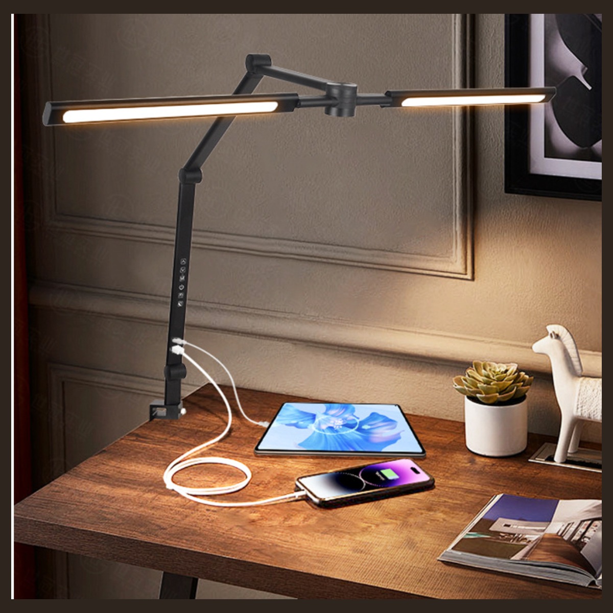
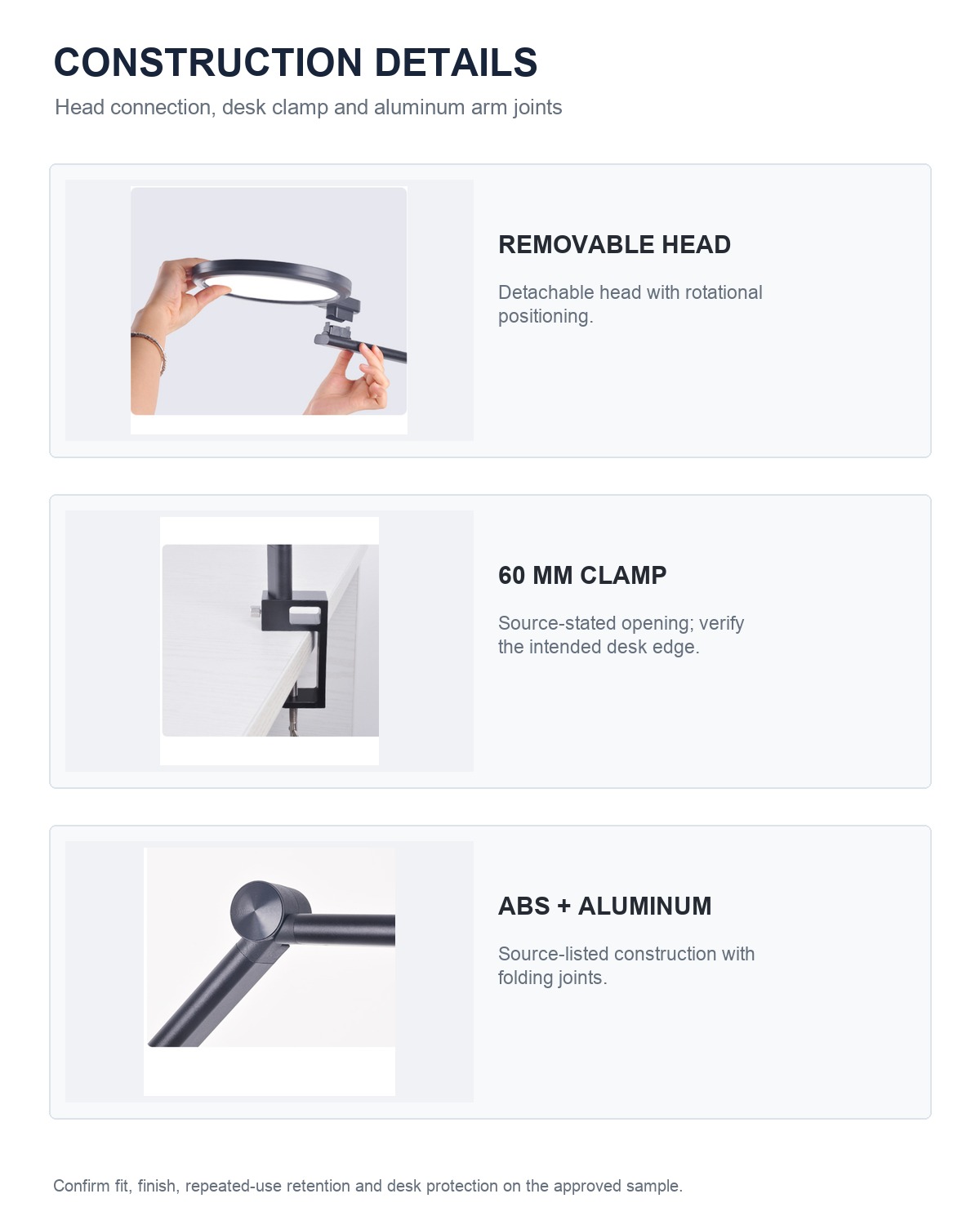
The RY229-B articulated clamp desk lamp is source-listed with four-axis folding, a removable circular head, and an approximately 60 mm clamp opening. Its test must control the representative desk edge and clamp position while cycling the articulated arm. Check head-connection retention, joint drift at maximum practical reach, cable routing, and mounting slip as separate observations. For desk geometry and surface checks, use the clamp desk lamp compatibility guide alongside the durability protocol.
7. Use different evidence at development, approval, and shipment
Durability testing serves different decisions during a project. During development, use multiple engineering samples to expose design variation and compare alternatives. Record every configuration change; a new washer, screw, resin, cable route, lubricant, arm length, or head mass can change the result.
Before mass production, connect the passed construction to the golden sample and controlled specification. Do not consume the only signed golden sample in a destructive endurance test. Keep a protected reference and clearly identify the separate tested units, their bill-of-material revision, and their relationship to the approved sample.
During production, use appropriate functional and workmanship checks to confirm the lot still matches the approved construction. A pre-shipment inspection can check joint feel, retention, drift, noise, cable condition, and sample comparison, but a short final inspection does not recreate a full development endurance program. Require a new durability review when a relevant component, material, supplier, tool, fastening process, or load geometry changes.
8. Make the measurement evidence auditable
List the sample IDs, model revision, test dates, operator, fixture drawing or photos, instrument IDs, calibration status, raw readings, planned interruptions, unplanned events, and failure images. Preserve results for each unit. If a laboratory is used, define the requested method and report format before sending samples.
ISO/IEC 17025:2017 sets general requirements for the competence, impartiality, and consistent operation of testing and calibration laboratories. A lab’s scope still needs to match the requested work. NIST’s metrological traceability guidance explains that traceability applies to a measurement result through a documented chain of calibrations, with each step contributing measurement uncertainty. A calibrated instrument alone does not prove that the chosen method, range, fixture, and uncertainty are fit for this decision.
For product safety, use the applicable requirements and qualified evaluation route for the destination market. IEC 60598-1:2024 covers general luminaire safety requirements and tests, while IEC 60598-2-4:2017 covers portable general-purpose luminaires. These standards provide a safety framework; they do not supply a universal buyer-specific hinge endurance count or prove that every commercial durability requirement has been met.
9. Copy this requirement block into the RFQ
| RFQ item | Buyer entry |
|---|---|
| Product and revision | Model, BOM/revision, drawing date, approved sample ID |
| Joint map | J1/J2/J3… location, axis, intended range, prohibited movement |
| Sample plan | Quantity, selection method, engineering or production source |
| Baseline | Range, force/torque method, drift time, play method, noise, appearance, cable, functions |
| One cycle | Start/end positions, joint sequence, speed, dwell, return, powered state |
| Total profile | Cycle count and rationale, checkpoints, rest periods, environment |
| Mounting and load | Base or desk fixture, clamp method, head/accessories, cables, applied electrical loads |
| Acceptance | Maximum drift/play change, force or torque window, noise rule, cosmetic and functional limits |
| Failure handling | Stop-test rule, notification, teardown permission, corrective-action and retest requirement |
| Report | Raw data per sample, photos/video, instruments, calibration, deviations, conclusion, sign-off |
Frequently asked questions
How many hinge cycles should a desk lamp pass?
There is no single defensible number for all desk lamps. Define the count from expected adjustment frequency, intended service period, warranty and safety risk, joint design, load, and prior evidence. The purchase requirement must include the movement profile and post-cycle limits, not only a count.
Is holding torque the only important result?
No. Position retention, free play, operating feel, noise, cracks, fastener movement, cable wear, electrical intermittency, clamp slip, and visible damage can all reject a sample even if its final torque remains within range.
Can the test run faster to save time?
Only after the accelerated speed has been assessed. Excessive speed can add heat, impact, and inertia or change lubricant and material behavior. Document the speed and show that the machine still represents the intended failure mechanisms.
Should a golden sample be cycle-tested?
Use units that match the approved construction, but preserve at least one controlled golden sample for later comparison. Identify which samples were endurance-tested because teardown or repeated cycling can make them unsuitable as the sole visual and functional reference.
Does an IEC 60598 report prove hinge lifetime?
No. Applicable IEC 60598 requirements support luminaire safety evaluation, but a buyer’s repeated-adjustment durability target needs its own defined profile, acceptance limits, product revision, and evidence. Ask the laboratory and supplier to state exactly what was tested.
Turn “durable” into an approval plan
Send RoyeLamp the lamp model, intended application, expected adjustment pattern, target market, warranty requirement, and any buyer-specific acceptance limits. We can discuss a sample and test plan tied to the ordered construction.
